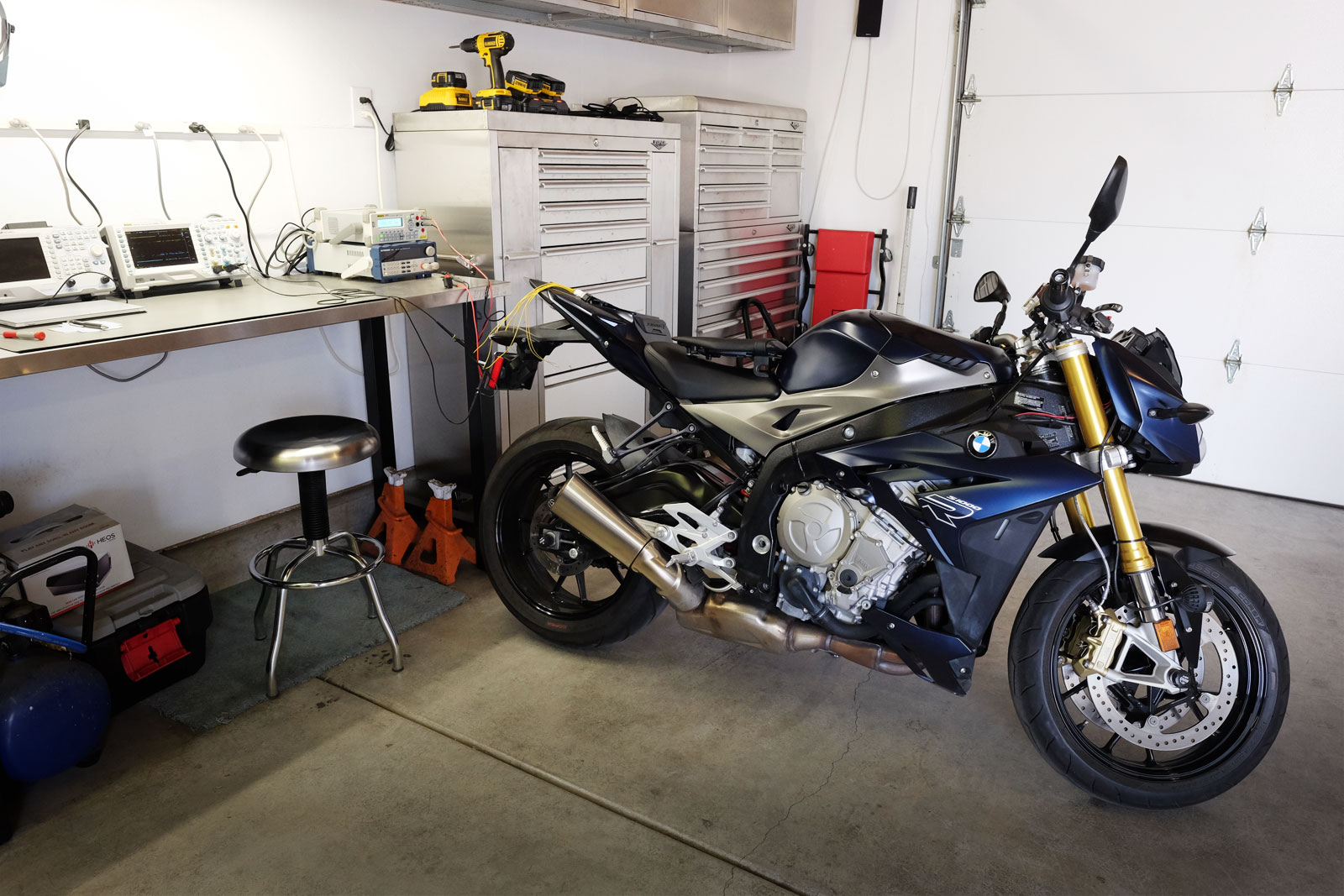
My BMW S1000R motorcycle is my favorite bike so far. I like everything about it except the headlights – when I turn on the high beams, both bulbs stay on, then after a few seconds the low beam turns off. Arg!!!! I want as much light as possible.
I have a factory service manual (FSM), but the FSM doesn’t have any wiring diagrams or technical information about the CANBUS. I’m going to have to hack it and I’ll show the steps I used to figure out the wiring. However this comes with a disclaimer – use this at your own risk. Messing around with your CANBUS can be life-threatening and could cost you a lot of $$$ if you break a controller.
All modern vehicles and now motorcycles are using CANBUS as a way to integrate different computers. For example, my S1000R has an engine controller, a light controller, and an ABS controller to name a few. These “talk” to each other by sending out messages. For example, the instrument cluster listens for messages about speed, RPM, the gear selected, etc. When I turn on the high beams, a message is sent that says “hey dude – the high beams are on”, the instrument cluster sees this message, and turns the high beam indicator on.
Therefore, the following steps are common for all CANBUS decoding:
- Find a CANBUS port
- Figure out the wiring – we need the CAN-High and CAN-Low signals
- Connect to a hardware decoder
- Run a packet capture
Find a CANBUS Port
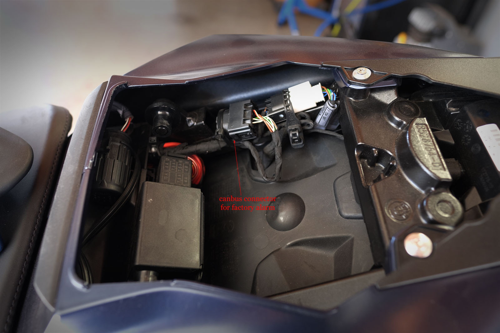
BMW motorcycles have a few CANBUS ports. Some are up front for accessories such as lighting and GPS. However, on the S1000R there is also a port under the passenger seat that is for the factory alarm option. I am going to use that.
Figure out the Wiring
CANBUS uses differential signalling over a pair of wires: CAN-High and CAN-Low. If no device is connected, the CANBUS needs to be terminated with a resistor. We can use this knowledge to help us figure things out.
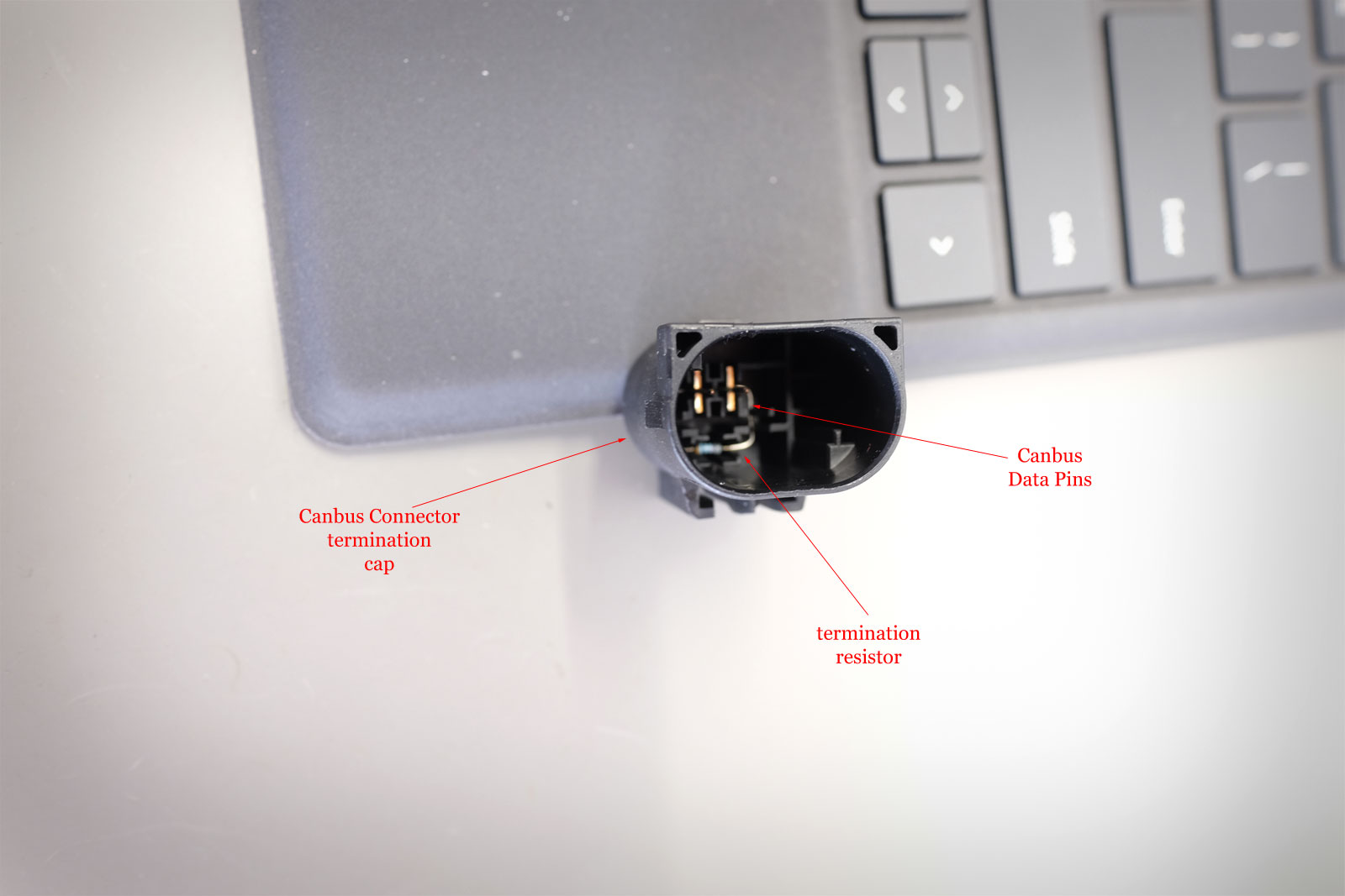
Looking into the cap, we can see two pins with a resistor connected between them. We can then look at the wiring on the port for the corresponding female pins. These are the CANBUS data pins.
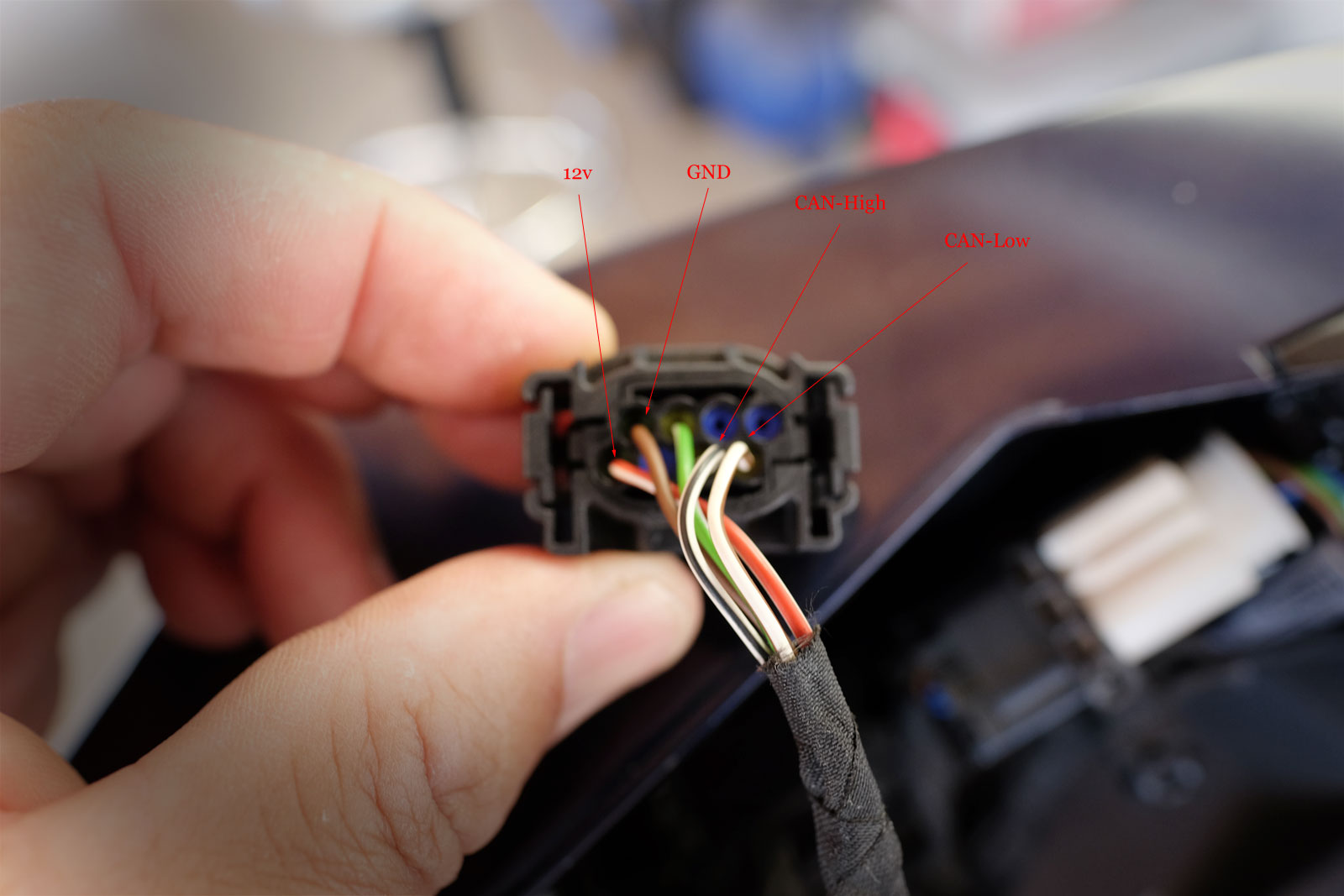
We know the two wires on the bottom row right are for CANBUS data. That leaves 3 wires to figure out.
You will need a multimeter for the next steps.
The red/white-stripe is a heavier gauge than the others. That’s a clue it is probably 12v power. Using a multimeter, set it to DC volts. Connect one probe to a good ground. Now use the other probe and check the pin connected to the red/white-stripe. It should be reading 12v constant (i.e. the ignition doesn’t need to be switched on.)
There is always a ground. The brown or green (or both) has to be ground. Set your multimeter to measure continuity. Probe the pin connected to the brown wire. Do you hear a tone? That means the brown wire is connected to ground.
Now we know power, ground, and the CANBUS data wires. All we need to do now is figure out which of the CANBUS data wires is CAN-H and CAN-L. We can’t use a multimeter because the data swings the voltages up/down too fast for a multimeter. We’ll need to “look” at the signals by using an Oscilloscope.
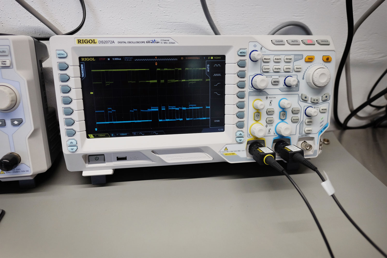
We will need a two-channel scope. Connect each channel to one of the CANBUS data wires – it doesn’t matter which.
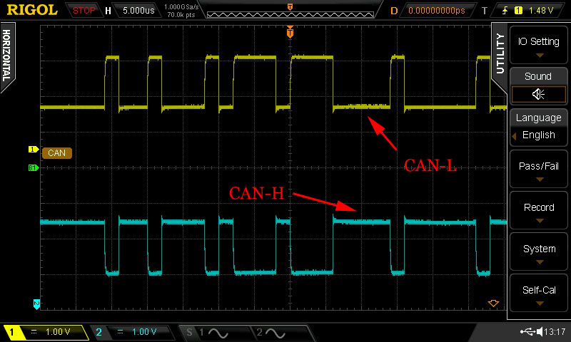
CANBUS uses differential signalling. This simply means when one wire goes low, the other wire goes high. The signals should look like a mirror opposite of each other. In the screenshot above, the bottom trace is the CAN-High signal. When there is no data, the CAN-High signal is “high” – the arrow points to it. When a bit is transmitted, it gets pulled “low” – that would be the dip.
Hardware Decoding and Packet Capture
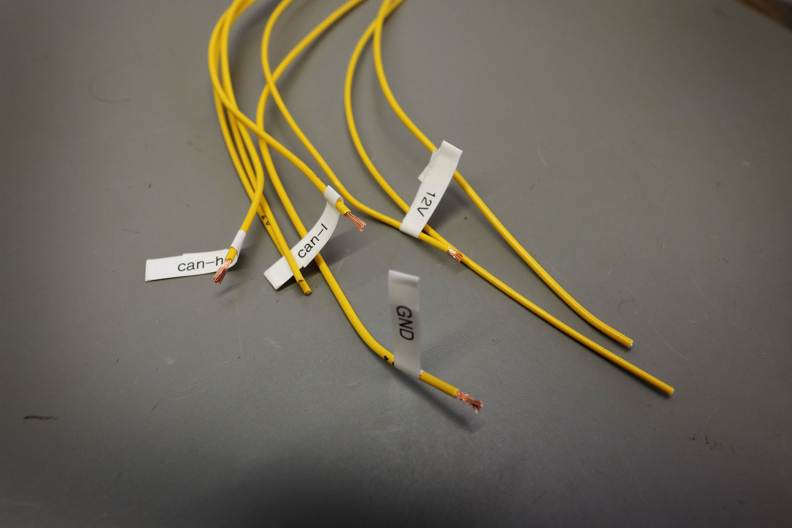
We now know all the wiring signals. Let’s label them to make it easier when we connect the hardware protocol decoder.
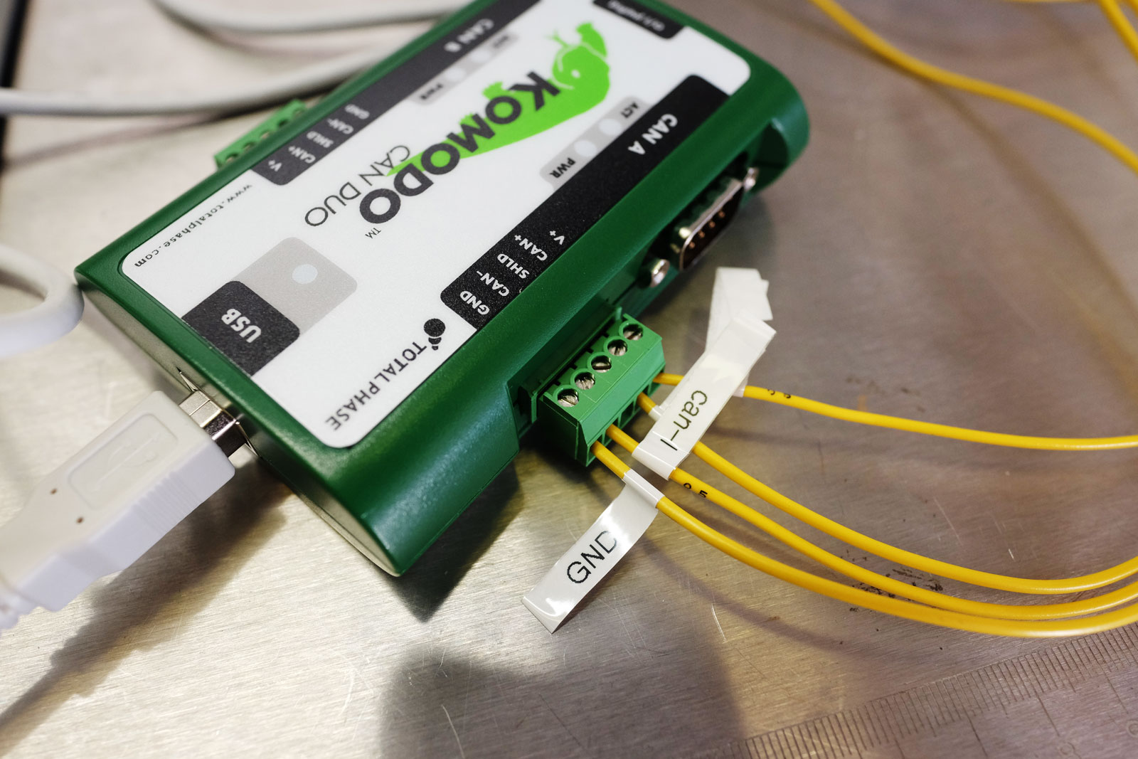
I am using a Komodo CANBUS Decoder. Connect the wires from the CANBUS plug to the corresponding screw terminal signals on the Komodo.
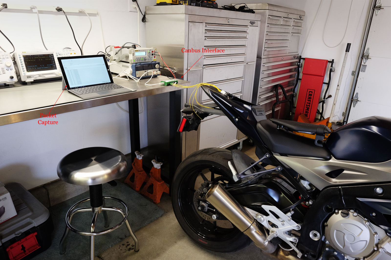
Once everything is connected, we’ll start a packet capture. The CANBUS runs at 500Kb. Turn the ignition on and packets should start flying. The next steps are to analyze the packets by using frequency distribution, trial and error testing, etc. I won’t go into detail on these steps. However, Keith Conger has done some great work on this and there is even a BMW Motorcycle CANBUS Message format document.
Notes and BMW CANBUS Technical Info
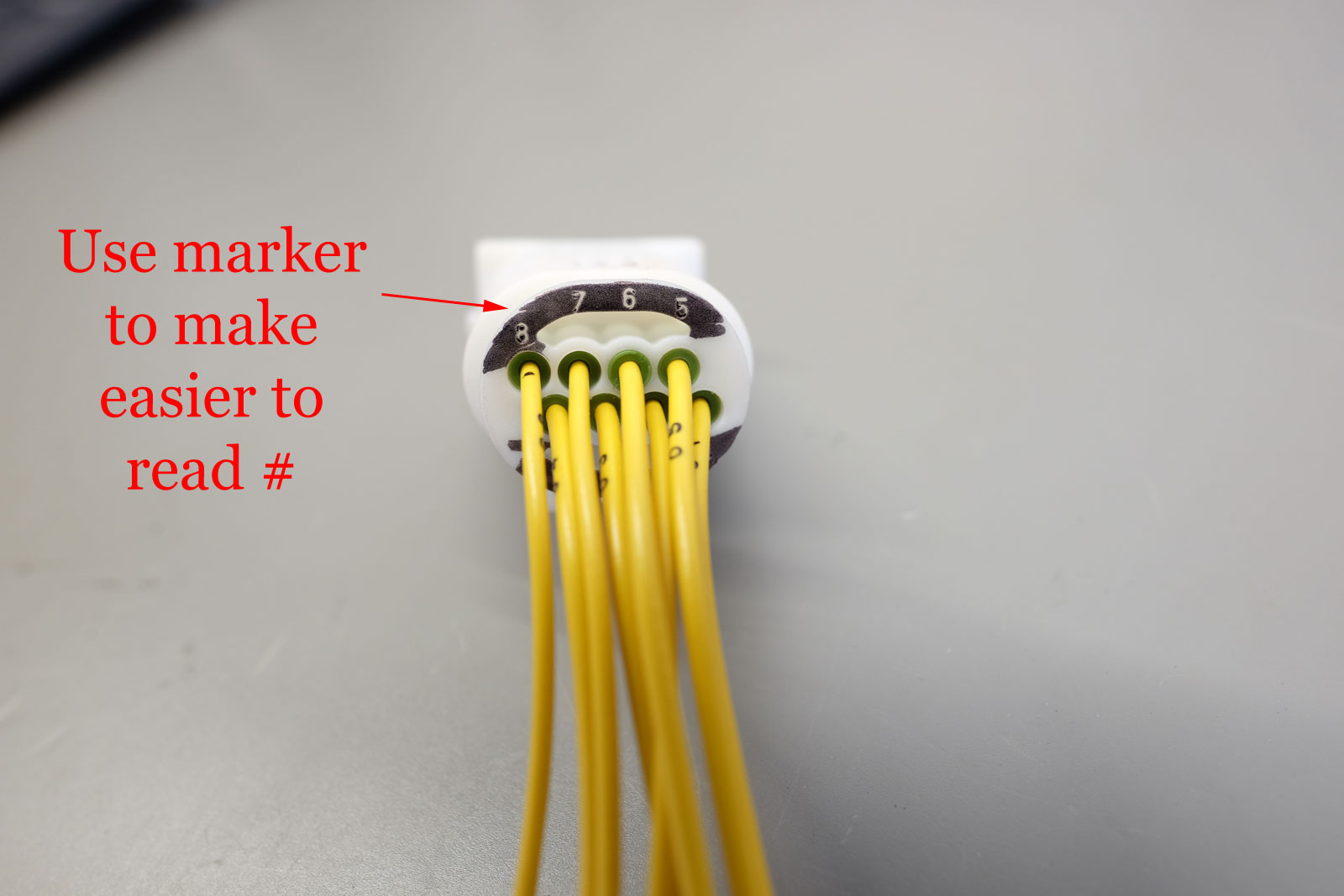
BMW Repair Cable – Part Number 83300413581. All pin number references related to the numbering on this cable.
BMW S1000R CANBUS Speed – 500Kb/s
Do not turn on the ignition with the CANBUS termination cap removed and nothing plugged into the CANBUS port. Otherwise, your bike will throw a diagnostic code. You will either need to go to the dealer or use a diagnostic tool such as the GS-911 to clear the fault code.
| BMW CANBUS Wiring/Pin Descriptions | ||
| Pin # | Wire Color | Description |
| 8 | Red/White Stripe | 12v power |
| 4 | Brown | Ground |
| 6 | White/Black Stripe | CAN-High |
| 5 | White/Brown Stripe | CAN-Low |