Raspberry Pi 4 Microk8s Kubernetes Clustering Gotchas

3 node raspberry pi 4 cluster

I’ve been running a few docker workloads on various stand-alone raspberry pi 4 hosts. This has worked well, but I decided to up my game a bit and setup a Kubernetes cluster. Why? Kubernetes is the container orchestration technology that is taking over the cloud and figured it would be a good learning opportunity to figure out how all the bits play together.

For my workloads, I need a 64 bit OS and I am using raspberry pi 4 8GB boards with a power-over-ethernet (POE) hat. I am using Ubuntu Server 64 bit and I am using Microk8s for the Kubernetes runtime. The tutorials are straight forward and I am not going to rehash that, but instead call out the gotchas to look out for.

CoreDNS

For my infrastructure stuff, I use DHCP reservations with long leases and make an internal DNS entries. This is a lot easier to centrally manage that doing static address assignments. I knew I was going to need k8 DNS support, so I did the following….

microk8s enable dns

And then when I moved my docker hosted container into a pod it failed. After a little troubleshooting to make sure there wasn’t any network layer issues, and validating that I could resolve external DNS names, I knew the problem was CoreDNS wasn’t pointed at my internal DNS servers. There are a couple ways to fix this…

# pass the dns server ips when enabling coredns 
microk8s enable dns:dns1, dns2

# or you can edit the configuration after-the-fact
microk8s kubectl -n kube-system edit configmap/coredns

Private Registry

I wanted to run a private registry to start with. Why? ISP connections can fail and it is also a fast way for me to experiment. Microk8s is the container orchestration layer, and it is using Docker for the container runtime. Docker by default will attempt to use HTTPs when connecting to the registry, which breaks with the private registry. You will see an error such as “…http: server gave HTTP response to HTTPS client.”

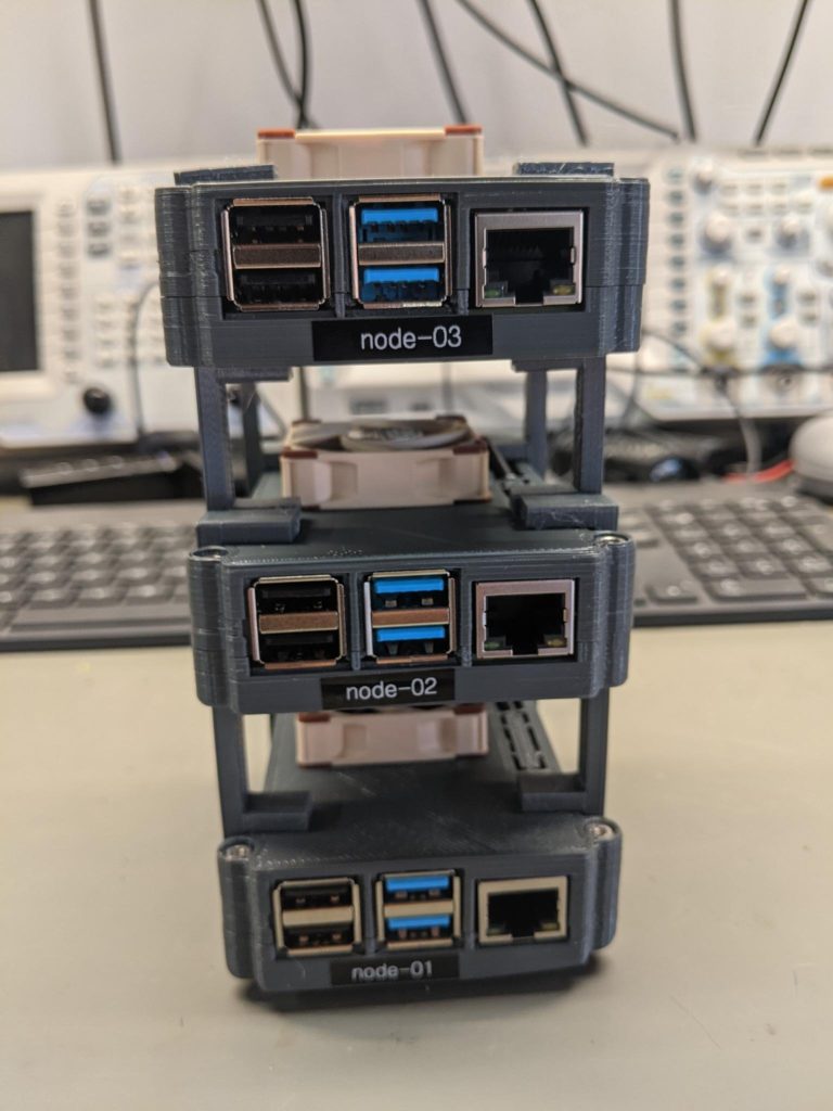
I am running a 3 node cluster, and I setup the registry storage on node-01. So we have to make some configuration edits…

# edit the docker /etc/docker/daemon.json file and add the ip address or FQDN to the registry host. I did this on each node of the cluster
{
  "insecure-registries" : ["xx.xx.xx.xx:32000"]
}

# restart docker
sudo systemclt restart docker

# now edit the container template and use the same 
# ip address/FQDN. I did this step on each node in 
# the cluster to make sure everything was consistent.
# The point of a cluster is to let the cluster consider 
# all resources when picking a host, so each node needs 
# to be able to pull the docker images if there is a 
# redeployment, scaling event, etc.
sudo nano /var/snap/microk8s/current/args/containerd-template.toml

 [plugins."io.containerd.grpc.v1.cri".registry.mirrors."xx.xx.xx.xx:32000"]
          endpoint = ["http://xx.xx.xx.xx:32000"]

# after making the edit/saving, restart the microk8s node
microk8s stop
microk8s start

I ported the leo ntp time server monitoring to run in the microk8s cluster. It has worked flawlessly until it croaked. The entire cluster was jacked up. I was using channel=1.20/stable which was the latest release at that time. I have since rebuilt the cluster to use channel=1.21/stable and everything has been bullet proof.

FlightAware ADS-B Dual 978 MHz + 1090 MHz Band-Pass SMA Filter

flightware ADS-B Dual 978 MHz + 1090 MHz Band-Pass SMA Filter

I plan to build an ADS-B tracker. However, I live in an RF noisy urban neighborhood, and all that noise can desense an RF receiver, so I bought this FlightAware Dual UAT+ADS-B filter. I put it on the spectrum analyzer and I measured a passband from ~930Mhz to ~1.2Ghz with ~1.5dB of insertion loss. Since this is all up in the gighertz range, my plan is to keep the antenna feedlines short by mounting a raspberry pi 4 in a weather-rated enclosure close to the antenna. I’ll power all of it by running a network cable with POE to the raspberry pi with a POE hat.

BMW S1000R Accessory Light Flasher – First Prototype

I built this about a year ago.  I prototyped a circuit that used an ATTiny85 microcontroller to drive a p-channel (high side) mosfet.  The idea was to use the microcontroller to strobe the Clearwater Darla LED accessory lights.

The circuit worked as expected, but that click-click-click-click noise is bad. I thought the functionality of the led “instant-on” was via a 12v signal to the dc-dc circuit in the led light, but it is actually a mechanical relay. Strobing anything mechanical is no bueno.

I  completely changed my strategy after this test.  A little experimenting and I discovered that the accessory lights are controlled by a PWM signal which controls the light intensity (low to full power).

Rigol Oscilloscope i2c Bus Decoding

I built a weather station last year. Even though I sprayed a conformal coating on the PCB to help it resist humidity exposure, the temp/humidity/barometric pressure sensor flaked out from exposure to the elements.  While fixing it, I decided to “geek out” a bit and hook the oscilloscope up to decode the i2c bus messages.  My notes for reference.

High Level:

  1. Connect probes, make sure they are setup correctly (10:1, etc.). Then set vertical scale and time-base.
  2. Set the triggering conditions to match the signal encoding
  3. Set the decode conditions to match the signal encoding
  4. Optional – use the event table to capture and export the data

Connections
Channel 1 probe to SCL (Clock)
Channel 2 probe to SDA (Data)

Scope Config
Set to 2v/div, 100us
Trigger – i2c, SCL->Channel 1, SDA->Channel 2, When->Start, Sweep->Auto
Decode – i2c, BusStatus->On, SCLK->Channel 1, SDA->Channel 2, SCL Threshold->1.80v, SDAThreshold->1.80v, Format->Hex (whatever is appropriate)

Enable the event table if you want to capture data which allows you to also export the data to a usb drive.

BMW S1000R Motorcycle CANBUS Hacking

My BMW S1000R motorcycle is my favorite bike so far. I like everything about it except the headlights – when I turn on the high beams, both bulbs stay on, then after a few seconds the low beam turns off.  Arg!!!! I want as much light as possible.

I have a factory service manual (FSM), but the FSM doesn’t have any wiring diagrams or technical information about the CANBUS.  I’m going to have to hack it and I’ll show the steps I used to figure out the wiring.  However this comes with a disclaimer – use this at your own risk. Messing around with your CANBUS can be life-threatening and could cost you a lot of $$$ if you break a controller. Continue reading “BMW S1000R Motorcycle CANBUS Hacking”

Messy Workbench

Messy Workbench
Messy Workbench

This is a picture of my workbench and some gizmo I was making last year.  I originally wanted to be an electronics engineer.  However, back in the dark ages of the 80’s, hardware geeking was much harder than today.  The cost of the test equipment was prohibitively expensive and way outside of my reach.  Access to parts was usually limited to what you could find at Radio Shack.  If you wanted broader access to parts, such as CPUs, memory, or other integrated circuitry your best bet was to ask for engineering samples.  I was a young starving student and I did not have the money nor patience required to get into hardware, so I shifted to software. Continue reading “Messy Workbench”

Garage Parking Assist – Part One

Intro

Ever since I outfitted my truck for the Zombie Apocalypse, parking it in my garage is something of a pain.  The front and rear bumpers have lengthened the wheelbase so I only have a few inches of margin – if I drive in too far I’ll hit the front wall, and if I don’t drive in far enough the garage door will hit the spare tire and refuse to close.

For years I put up with this until the hassle overcame my laziness factor.  I could have hung a tennis ball from the ceiling, but I’ve got a pretty cool garage “man cave” and a dangling tennis ball isn’t cool.  Plus, I’ve got some geek cred I need to maintain, I can build it myself, and more importantly maybe this can teach/inspire someone else along the way.

I’ve organized this into a two part series.  Part one will give you some background info, instructions on bread-boarding (prototyping) the circuit, and getting the software flashed to the circuit.  Additionally, I’ll point out some of the more important details in the software and give reasons why this was done.

While you might see some of the electronic equipment on my bench, don’t let that stop you.  All you need is a multimeter, and you don’t really need that unless stuff goes whacko.  Start with a simple breadboard and hookup wire.  If you decide to make this more permanent, I’ve included links to “perma-proto” boards.  These look just like the breadboard you are using, but you can solder stuff to them. Continue reading “Garage Parking Assist – Part One”