
Intro
Ever since I outfitted my truck for the Zombie Apocalypse, parking it in my garage is something of a pain. The front and rear bumpers have lengthened the wheelbase so I only have a few inches of margin – if I drive in too far I’ll hit the front wall, and if I don’t drive in far enough the garage door will hit the spare tire and refuse to close.
For years I put up with this until the hassle overcame my laziness factor. I could have hung a tennis ball from the ceiling, but I’ve got a pretty cool garage “man cave” and a dangling tennis ball isn’t cool. Plus, I’ve got some geek cred I need to maintain, I can build it myself, and more importantly maybe this can teach/inspire someone else along the way.
I’ve organized this into a two part series. Part one will give you some background info, instructions on bread-boarding (prototyping) the circuit, and getting the software flashed to the circuit. Additionally, I’ll point out some of the more important details in the software and give reasons why this was done.
While you might see some of the electronic equipment on my bench, don’t let that stop you. All you need is a multimeter, and you don’t really need that unless stuff goes whacko. Start with a simple breadboard and hookup wire. If you decide to make this more permanent, I’ve included links to “perma-proto” boards. These look just like the breadboard you are using, but you can solder stuff to them.
What to Build
You hang a tennis ball from the ceiling and once it touches your windshield, you know you’ve driven in far enough. I wanted something that will measure distance and use a traffic style signal:
- Green – Keep going, no danger of hitting anything.
- Yellow – Slow down, it is almost time to stop.
- Red – Stop. This is the tennis ball touching your window. There should be a safety margin built in to allow for reaction time.
- Flashing Red – Exceeded the stop safety margin and if you keep driving forward very bad things will happen.
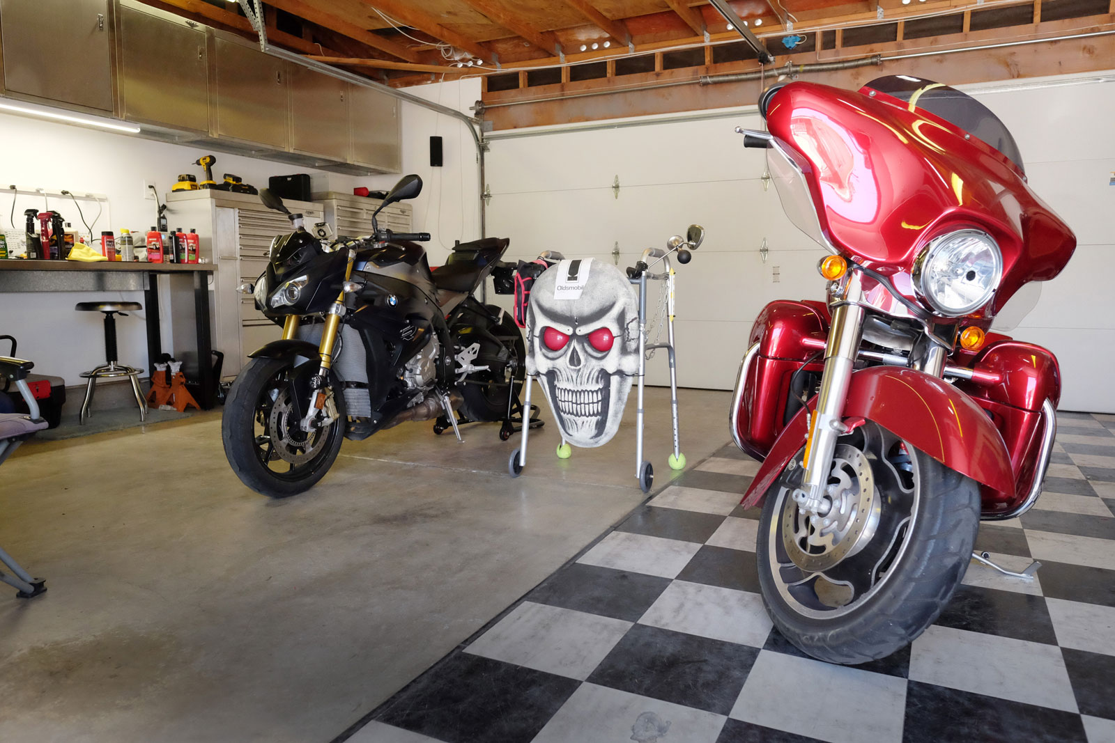
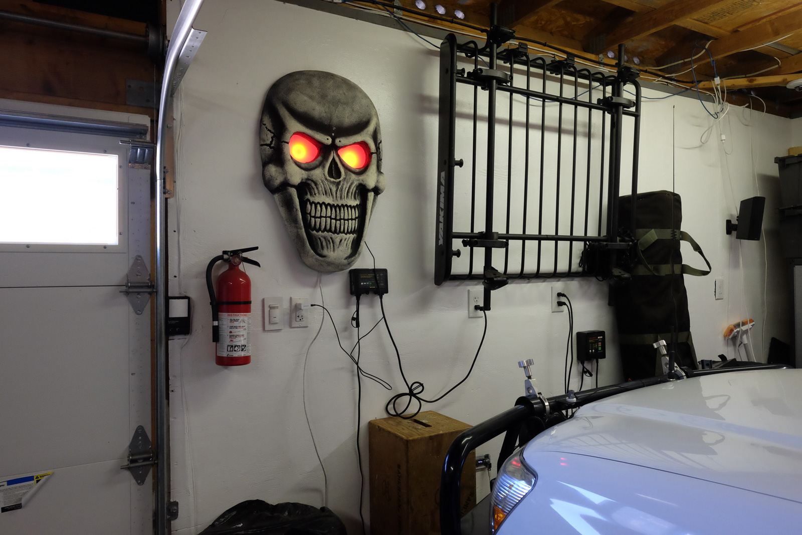
Next, I wanted it to look cool, unobtrusive, and more like art vs. having function. My peeps did a great prank on me years back. They know I like motorcycles, so they tricked out a walker with a skull, horn, rear-view mirror, Ensure, Depends, and anything else that drove the point home I’m old. I decided the skull was perfect. While the walker is gone, part of it still lives on.
Parts
This is the complete parts list except for the skull since I had that on-hand. Plus you might want to mount this in something that better fits your tastes.
VL53L0x Laser time-of-flight sensor 50mm-1200mm range
https://www.adafruit.com/product/3317
Adafruit WICED WiFi Feather – STM32F205 with Cypress WICED WiFi
NOTE – you can use a cheaper micro without the wifi
https://www.adafruit.com/product/3056
Adafruit Feather 32u4 Basic Proto – this is a good substitute
if you don’t want the cost/complexity of the WICED feather
https://www.adafruit.com/product/2771
FeatherWing OLED – 128×32 OLED Add-on
NOTE – not essential and the code can be built without OLED support
https://www.adafruit.com/product/2900
Adafruit NeoPixel Ring – 16 x 5050 RGBW LEDs w/ Integrated Drivers
Cool White – ~6000K
https://www.adafruit.com/product/2856
2 Pcs RJ45 8-pin Connector (8P8C) and Breakout Board Kit
NOTE – I separated the sensor and micro into two different pcb’s
so I could have mounting flexibility. I use a small CAT5 Ethernet
cable as an i2c bus between the pcb’s
https://www.amazon.com/gp/product/B0156JXSF8/
2 Adafruit Perma-Proto Mint Tin Size Breadboard PCB
https://www.adafruit.com/product/723
CAT-5 Network cable.
Basic Circuit and Sofware
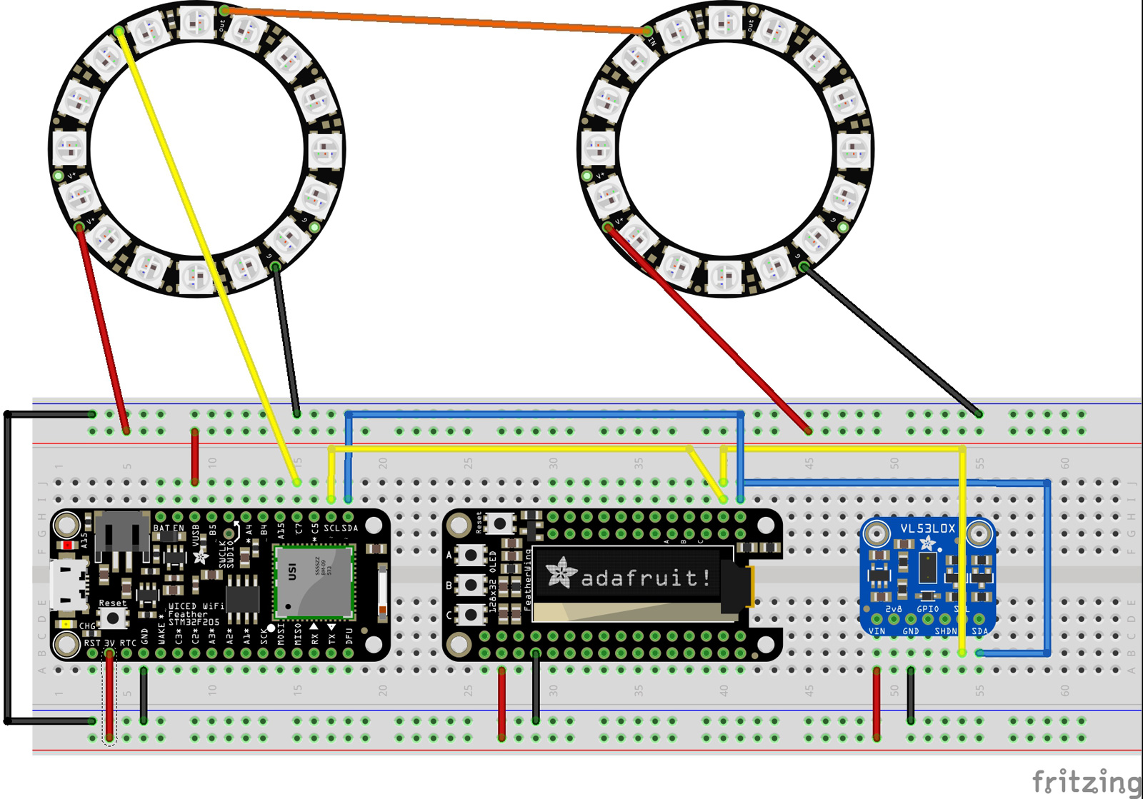
This is a good circuit to try if you’re new to electronics. I’ve split the breadboard to have a 5v power rail on the top for the Neopixel Rings, and a 3.3v power rail on the bottom for the sensor and OLED display. Just remember – if it isn’t round (Neopixel Rings), then power it from down below.
If you hook any of the i2c or GPIO pins up wrong, it shouldn’t give you the satisfying smell of electronic smoke. You won’t burn anything up, but stuff won’t work. Double check your wiring and try again.
Software
Once you build the circuit, you can download the code from my git-hub project page: Garage Parking Assist. You will need to install a couple of libraries. Make sure to follow the prerequisites and build instructions there.
I intentionally wrote the code to be readable for peeps new to programming/Arduino/IoT stuff. I’ll discuss some of the most important pieces, but I’ll leave out the animations for you to tinker with and explore.
At a high level the overall algorithm is to:
- Get a distance reading from the lidar sensor
- Compare this reading against a predetermined set of ranges
- Perform some sort of animation based on the range.
void loop()
{
  flashActivityLed();

  uint16_t rawdistance = sensor.readRangeContinuousMillimeters();

  if (rawdistance > 8000)
  {
    pixelsRingSpinClockwise(COLOR_GREEN);
    oledPrint("OUT RANGE", 2);
    return;
  }

  Serial.print("raw distance: " );
  Serial.print(rawdistance);
  Serial.print("mm ");

  if (sensor.timeoutOccurred())
  {
    Serial.print(" TIMEOUT");
  }

  uint16_t distance = smoothing(rawdistance);

  oledDisplayDistance(distance);

  animatePixelDisplayByDistance(distance);

  Serial.println();
}
This overall algorithm strategy is implemented in the loop() function. One thing to call out is why I am using a rawdistance measurement and something called “smoothing.” What usually happens when you read sensors is the values change a little bit from read to read. This is also called jitter. For instance, if the lidar sensor was pointed at a fixed object precisely 500mm from it, the first read might be 495mm, then next read might be 501mm, etc. We will use a concept called smoothing to overcome the jitter, so let’s look at that function.
uint16_t smoothing( uint16_t reading )
{
  // The max amount that can change
  // between subsequent readings
  const int16_t RANGE_DETLA_CHANGE = 15;

  const int16_t NO_READING_SET = -1;

  // TODO - need to put in bounds checking/overflow logic

  static int count = 0;
  static float avg = 0;
  static int sum = 0;
  static int lastreading = NO_READING_SET;

  if ( lastreading == NO_READING_SET  )
  {
    lastreading = reading;
  }

  int deviation = abs(reading - lastreading);

  if ( deviation >= RANGE_DETLA_CHANGE )
  {
    Serial.println( "Big change in range detected, reseting smothing." );

    // A big change in range happened, so we need
    // to reset the smoothing
    count = 0;
    sum   = 0;
    avg   = 0;
    lastreading = NO_READING_SET;
  }

  count++;
  sum += reading;
  avg = sum / (float)count;

  Serial.print( "Smoothed: " );
  Serial.println( avg );

  return avg;
}
There are a couple of challenges that we need to consider with this smoothing function: The first is acquiring the distance of moving vehicle as you are driving into your garage, and the second is when the vehicle is parked/stationary.
Line 5
What we can do is use a delta value to define how much change should be considered as jitter. I came up with 15mm by running a bunch of fixed distance tests and capturing the range of values produced. These tests showed about 10mm was the deviation, and I added an extra 5mm for a safety margin.
Line 21..23
Next, we need to figure out how much distance has changed between readings. We don’t care if the change was moving closer to the sensor or further away, we only care about the magnitude. This is why we are using an absolute value.
If the deviation exceeds our delta, then we should assume the vehicle is still moving, and we invalidate all of our previous averages and calculations.
Line 35
If we make it down to line 35, then what we do is add our new distance value to our previous summed distance values, and recalculate an average. We’ve smoothed our distance measurement by using a running average.
The next part of the code to discuss is the animatePixelDisplayByDistance() function.
void animatePixelDisplayByDistance(uint16_t distance)
{
  const uint16_t DISTANCE_MM_WARNING = 762;
  const uint16_t DISTANCE_MM_STOP = 583;
  const uint16_t DISTANCE_MM_CRITICAL = 483;
  const uint16_t DISTANCE_MM_OK = DISTANCE_MM_WARNING + 1;

  if ( distance <= DISTANCE_MM_CRITICAL )
  {
    pixelsAllStrobe(COLOR_RED);
    return;
  }

  if ( distance <= DISTANCE_MM_STOP )
  {
    pixelsAllOn(COLOR_RED);
    return;
  }

  if ( distance <= DISTANCE_MM_WARNING )
  {
    pixelsAllOn(COLOR_YELLOW);
    return;
  }

  if ( distance >= DISTANCE_MM_OK )
  {
    pixelsAllPulse(COLOR_GREEN);
  }
}
The constants DISTANCE_MM_* are used to define the various critical distances. I came up with these values by measuring distances to where I planned to mount the sensor, and calculating if the garage door would clear my rear bumper. You will want to adjust these values to what makes sense for the size of your garage and vehicle.
We will need to account for reaction time – the time it takes you to see something, your brain to process it, and your foot to press the brake to stop the vehicle. I’ve built 100mm difference between the DISTANCE_MM_STOP and DISTANCE_MM_CRITICAL to allow for reaction time.
Up Next – Part Two
If you’ve made it this far you should be able to prototype the circuit, build the software, and flash the microcontroller. Once we get things working the way we expect, Part Two will discuss how to make things more permanent and visually interesting.