Rigol Oscilloscope i2c Bus Decoding

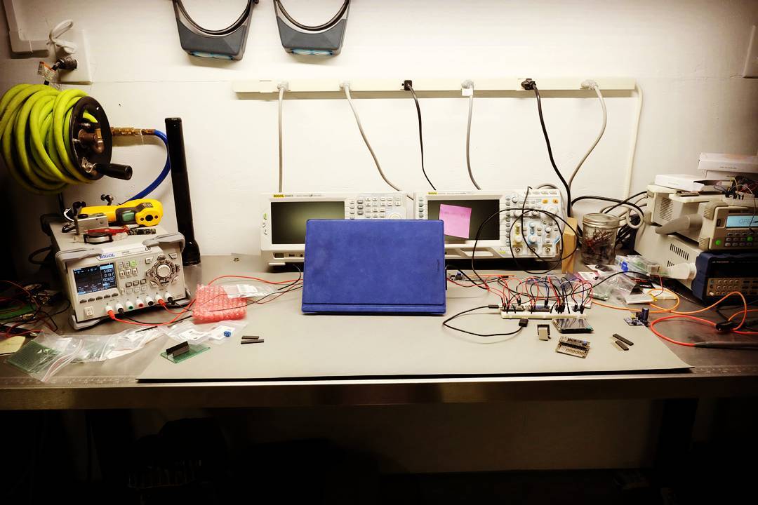
I built a weather station last year. Even though I sprayed a conformal coating on the PCB to help it resist humidity exposure, the temp/humidity/barometric pressure sensor flaked out from exposure to the elements.  While fixing it, I decided to “geek out” a bit and hook the oscilloscope up to decode the i2c bus messages.  My notes for reference.

High Level:

  1. Connect probes, make sure they are setup correctly (10:1, etc.). Then set vertical scale and time-base.
  2. Set the triggering conditions to match the signal encoding
  3. Set the decode conditions to match the signal encoding
  4. Optional – use the event table to capture and export the data

Connections
Channel 1 probe to SCL (Clock)
Channel 2 probe to SDA (Data)

Scope Config
Set to 2v/div, 100us
Trigger – i2c, SCL->Channel 1, SDA->Channel 2, When->Start, Sweep->Auto
Decode – i2c, BusStatus->On, SCLK->Channel 1, SDA->Channel 2, SCL Threshold->1.80v, SDAThreshold->1.80v, Format->Hex (whatever is appropriate)

Enable the event table if you want to capture data which allows you to also export the data to a usb drive.

Messy Workbench

Messy Workbench
Messy Workbench

This is a picture of my workbench and some gizmo I was making last year.  I originally wanted to be an electronics engineer.  However, back in the dark ages of the 80’s, hardware geeking was much harder than today.  The cost of the test equipment was prohibitively expensive and way outside of my reach.  Access to parts was usually limited to what you could find at Radio Shack.  If you wanted broader access to parts, such as CPUs, memory, or other integrated circuitry your best bet was to ask for engineering samples.  I was a young starving student and I did not have the money nor patience required to get into hardware, so I shifted to software. Continue reading “Messy Workbench”

Garage Parking Assist – Part One

Intro

Ever since I outfitted my truck for the Zombie Apocalypse, parking it in my garage is something of a pain.  The front and rear bumpers have lengthened the wheelbase so I only have a few inches of margin – if I drive in too far I’ll hit the front wall, and if I don’t drive in far enough the garage door will hit the spare tire and refuse to close.

For years I put up with this until the hassle overcame my laziness factor.  I could have hung a tennis ball from the ceiling, but I’ve got a pretty cool garage “man cave” and a dangling tennis ball isn’t cool.  Plus, I’ve got some geek cred I need to maintain, I can build it myself, and more importantly maybe this can teach/inspire someone else along the way.

I’ve organized this into a two part series.  Part one will give you some background info, instructions on bread-boarding (prototyping) the circuit, and getting the software flashed to the circuit.  Additionally, I’ll point out some of the more important details in the software and give reasons why this was done.

While you might see some of the electronic equipment on my bench, don’t let that stop you.  All you need is a multimeter, and you don’t really need that unless stuff goes whacko.  Start with a simple breadboard and hookup wire.  If you decide to make this more permanent, I’ve included links to “perma-proto” boards.  These look just like the breadboard you are using, but you can solder stuff to them. Continue reading “Garage Parking Assist – Part One”