
Recap
We’ve prototyped the circuit, built the software, and flashed the microcontroller. Everything should be working correctly, but it just looks like a pile-of-parts and wires. Now we need to make this more permanent and finished.
For a refresher, please see Part One of this series.
Skull Hacking
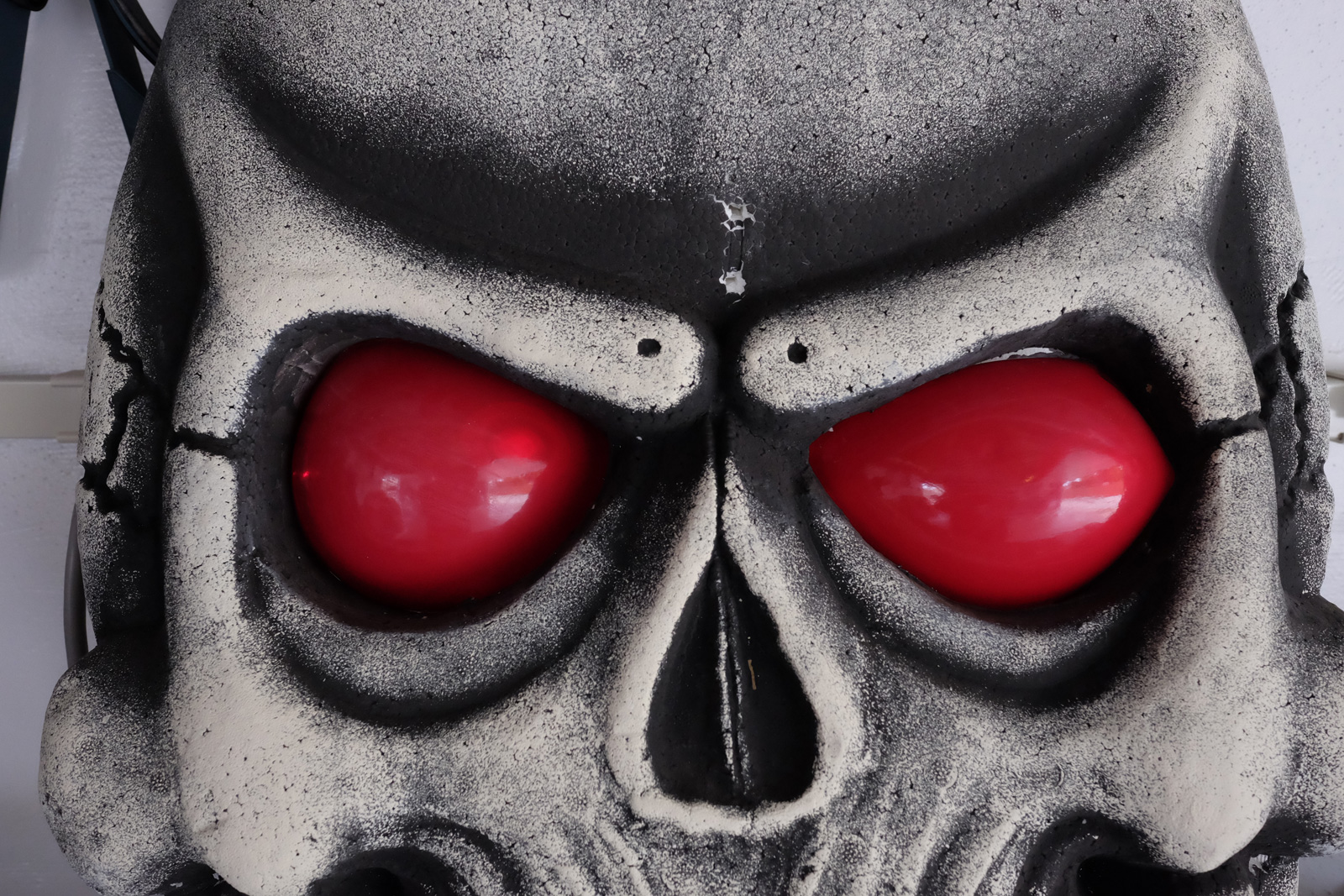
I am re-purposing the skull my peeps used for a prank. The skull has red colored lenses for eyes and used a white LED for illumination. This setup won’t display the animated colors, so the lenses need to be hacked and replaced with something that will diffuse colors. I bought some cheap flexible cutting boards off Amazon to use as the new lens material.
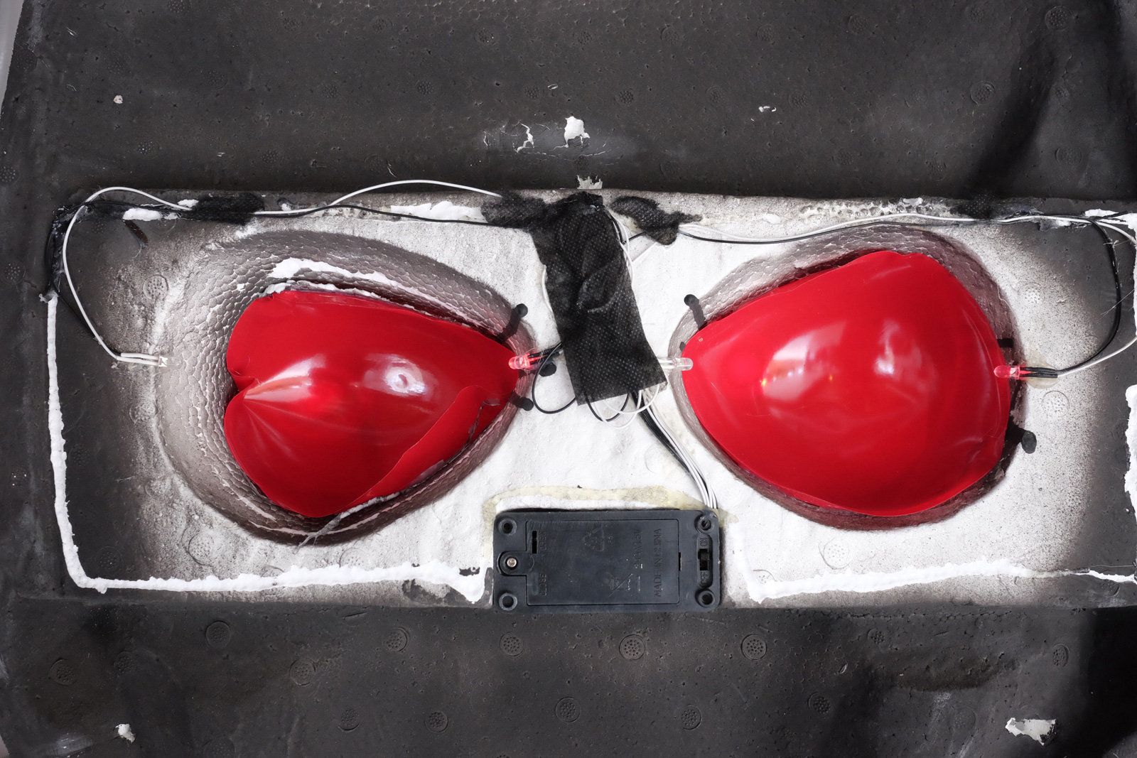
The first step is to remove the existing lenses and wiring. Most of the parts were held in place with hot glue drops to the Styrofoam and pulled right out.
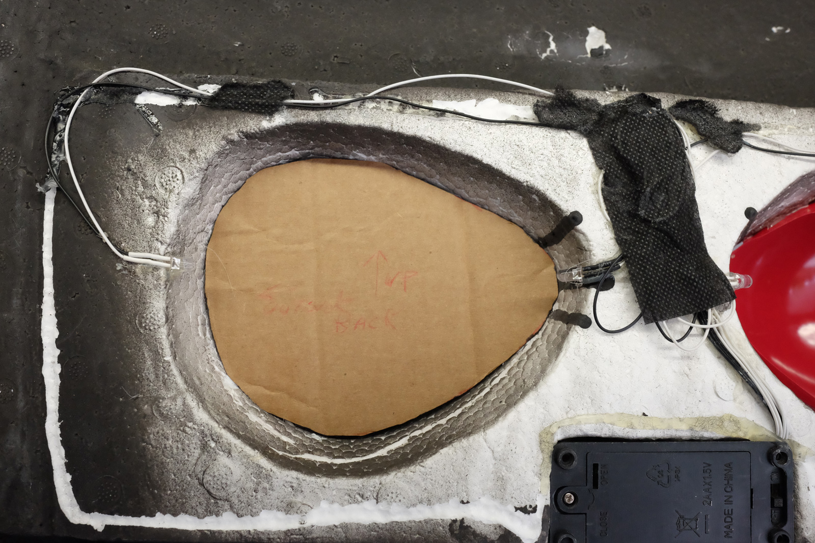
The next step is to make a cardboard template. Take some cardboard, trim it, and check for fitment. Keep trimming it until it sits at the proper depth with no huge gaps. A little bit of a gap is OK – the new lens can be inserted deep enough to take out the gap.
Use a Sharpie and trace an outline of the template onto the cutting board. Then use a pair of scissors to cut out the new lens and insert it into the skull’s eye socket.
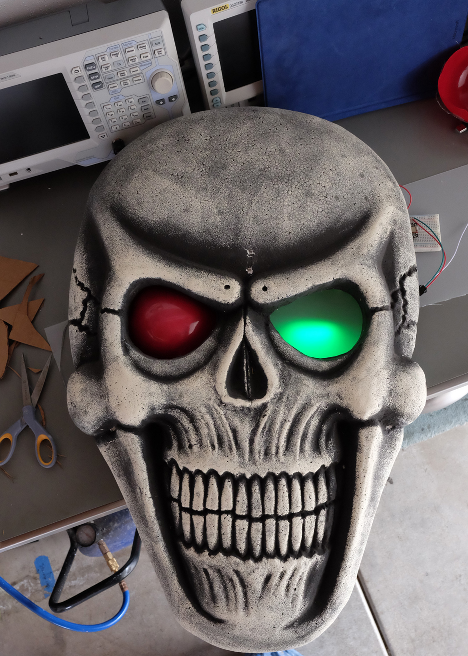
After I installed the lens, you will want to perform a fitment test. I wanted to see how well the light was diffusing, aesthetics, etc. before moving on to the next steps of mounting the LEDs behind the eyes.
Mount the LED Rings
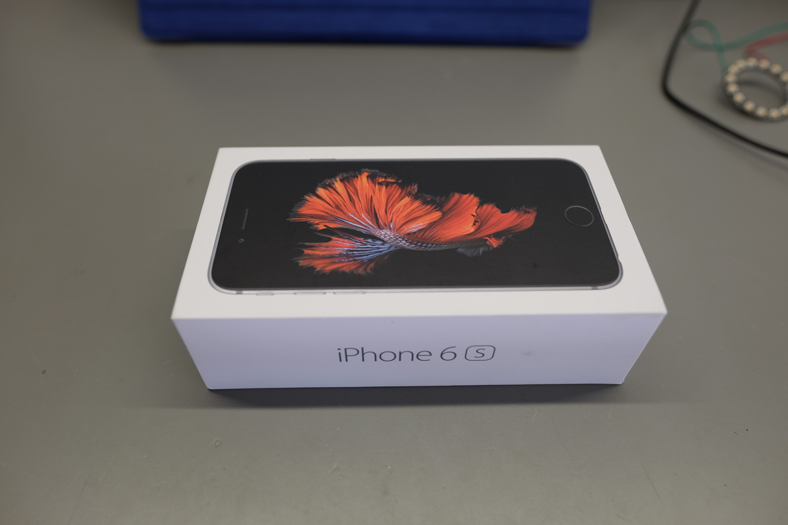
I was at a friend’s house and noticed an iPhone box. Apple packaging is top notch, using dense and structurally strong cardboard. This would be perfect to use for building a mount for the Neopixel rings. Plus, there is something pleasantly satisfying hacking anything Apple.
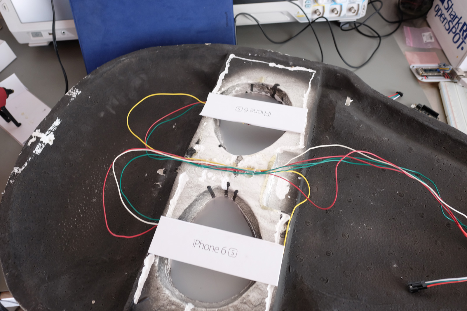
I cut the sides of the box, and used a hot glue gun to mount the Neopixel rings. I daisy-chained the Neopixel rings together, which means pixels 0..15 are for one eye, and 16..31 are for the other. Therefore, if you ever plan to do eye-specific animation, make sure to keep track of which eye is left/right, and mount accordingly. I used hot glue to attach the mounts behind the appropriate eye.
Main Board
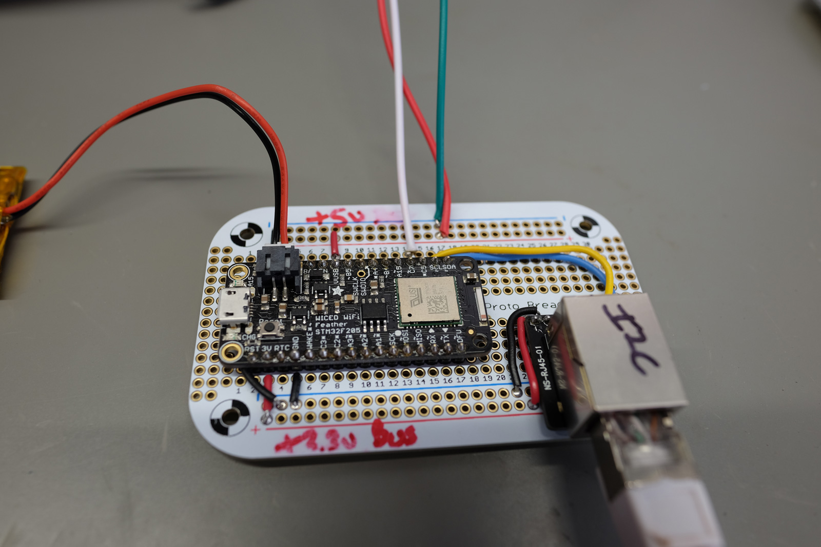
I wanted the freedom to hang the skull anywhere on the wall, but the lidar sensor needed specific placement, so I’m going to have to separate the two into their own boards: The main board and the sensor board. Because I have a bunch of CAT-5 network cable in my junk box, I used an 8P8C/RG-45 connector on each board. I wired it so I can bus (transfer) power/data over the CAT-5 connector to the sensor board.
I soldered an Adafruit Feather to a proto-board, and made distinct 5v/3.3v rails. In hindsight, I should have soldered in female headers so I can swap the Feather for a different board in the future. The 5v rail is for the Neopixel rings, and the 3.3v rail is for the I2C data/power bus to the lidar sensor.
I used circuit board standoffs that I hot glued to the skull. I placed the stand offs thru each corner of the board, and a nut screwed down from the top. This will make it easier to tear apart if I get a desire to change things up in the future.
Sensor Board
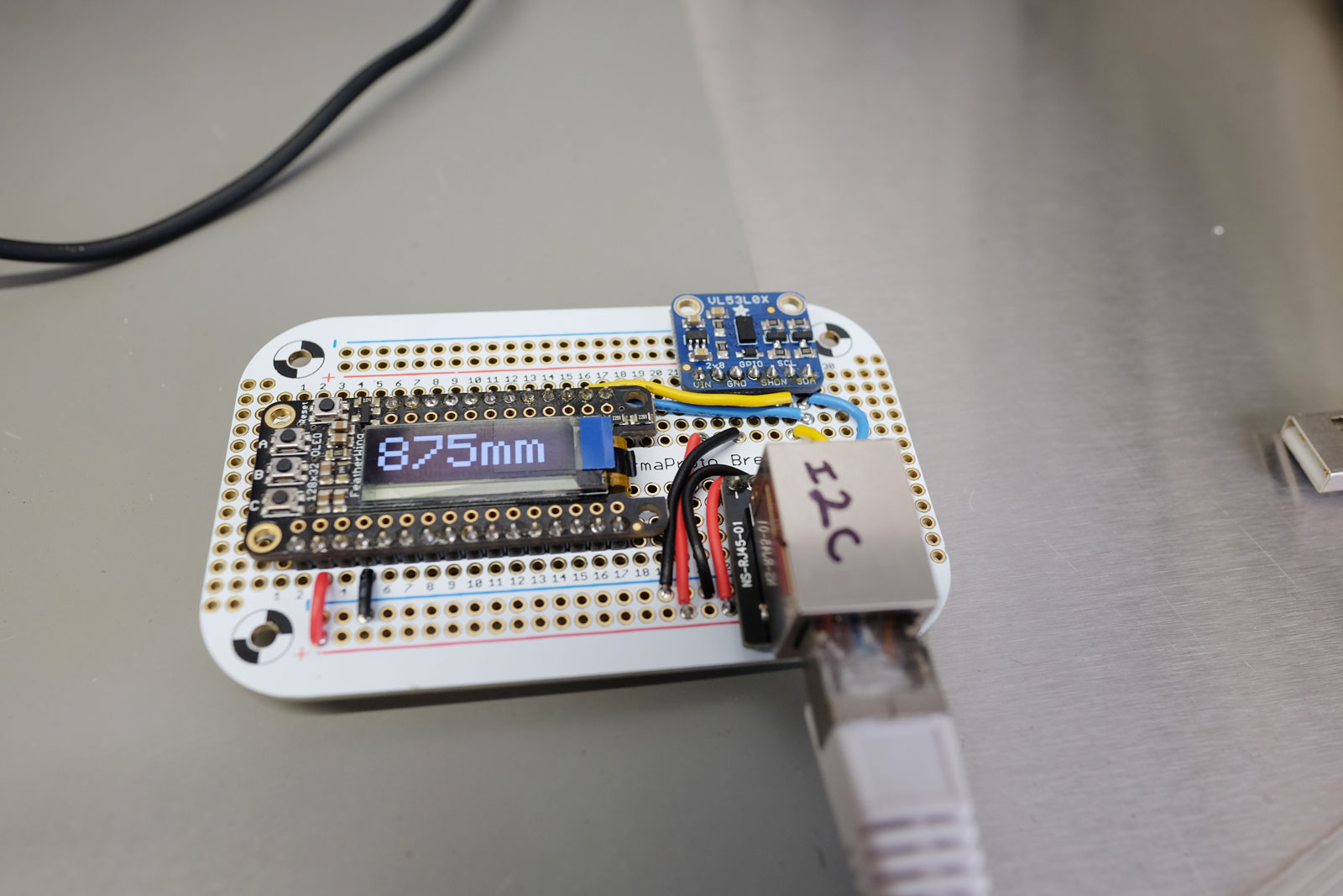
The sensor board contains the lidar sensor (blue), and an OLED display for diagnostic/calibration. Power and data come over the i2C bus via the CAT-5 cable. What’s nice about using i2c in this design is it simplifies signaling. For instance, while I can’t see the display when I’m driving into the garage, I figured it would be useful for diagnostics. Adding it was trivial – all it needed was 4 wires, 2 for power and 2 for i2c. If I wasn’t using i2c and it was more involved, I probably would have skipped adding the display.
This board will be mounted on the wall positioned so the lidar hits my front bumper. I targeted the license plate because it’s highly reflective.
Putting It All Together
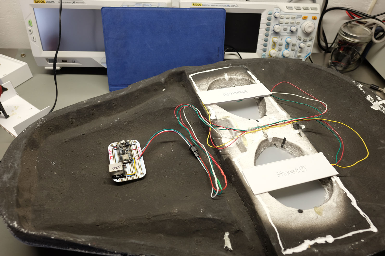
We are using a microcontroller, a lidar sensor to measure distance, and some Neopixel rings. The microcontroller reads distance measurements from the lidar sensor, and then animates the Neopixel rings. All of this gets mounted on perma-proto boards.
We take the main board and Neopixel rings, and mount this into the skull. The sensor board gets mounted to the wall, and it’s connected to the main board with cheap CAT-5 cable.
Now we have a cool skull on the wall. To passers buy, it’s just some sort of biker wall art. But secretly it will help you park your vehicle in the garage.